Demo Input/Output Kit
1. Introduction
Who is this tutorial for?
This tutorial is intended for developers and makers who want to learn how to use analog and digital I/O with the OI-Demo Input/Output kit. Whether you are new to embedded systems or already familiar with Arduino-style programming, this guide will walk you through each part of the project step by step.
Prerequisites
Basic knowledge of C++ and Arduino programming
A computer with Visual Studio Code installed
The OpenIndus VS Code extension installed - see Environment Installation
SiliconLabs USB driver installed (CP2102N - USB↔UART)
Familiarity with Start coding
What will you learn?
How to read values from an I²C temperature and humidity sensor
How to display information on an I²C OLED screen
How to manage input events with interrupts and FreeRTOS tasks
How to read analog voltages and 4-20 mA current signals
How to drive an RGB LED and a white LED using PWM outputs
2. Discover your kit
The Demo Input/Output kit combines sensors and actuators to demonstrate the full range of analog and digital capabilities of the OI-Mixed module, supervised by an OI-Core master module.
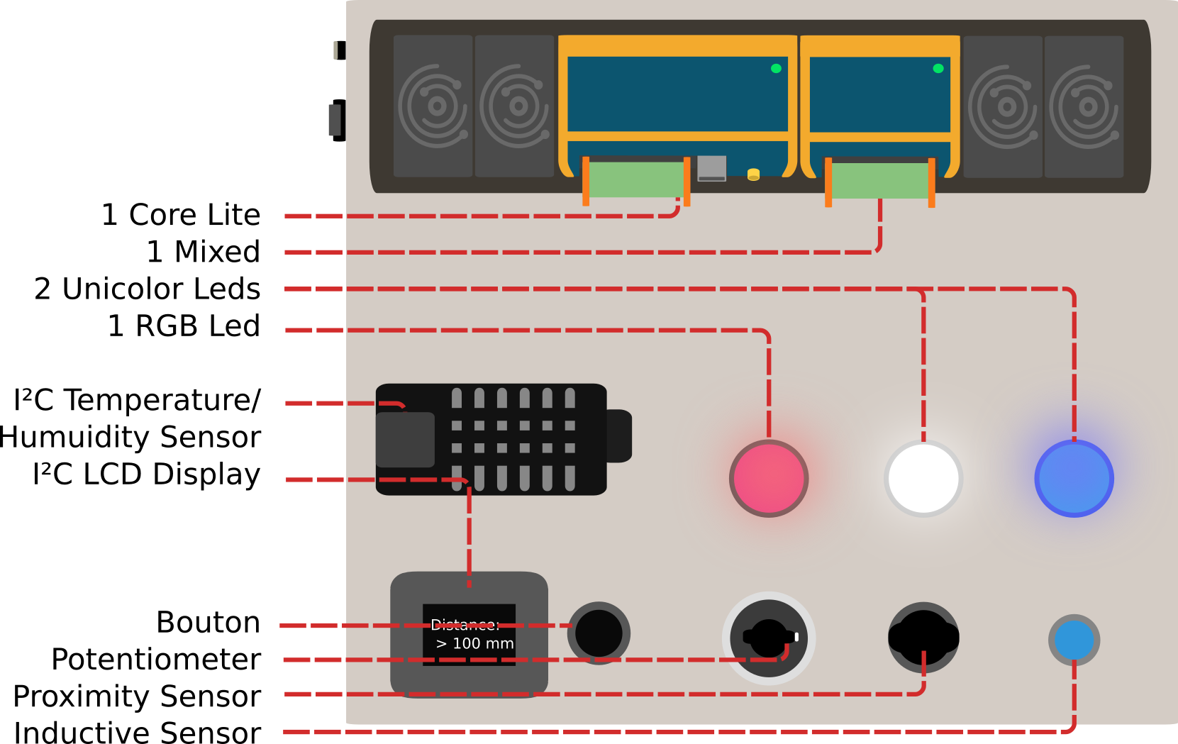
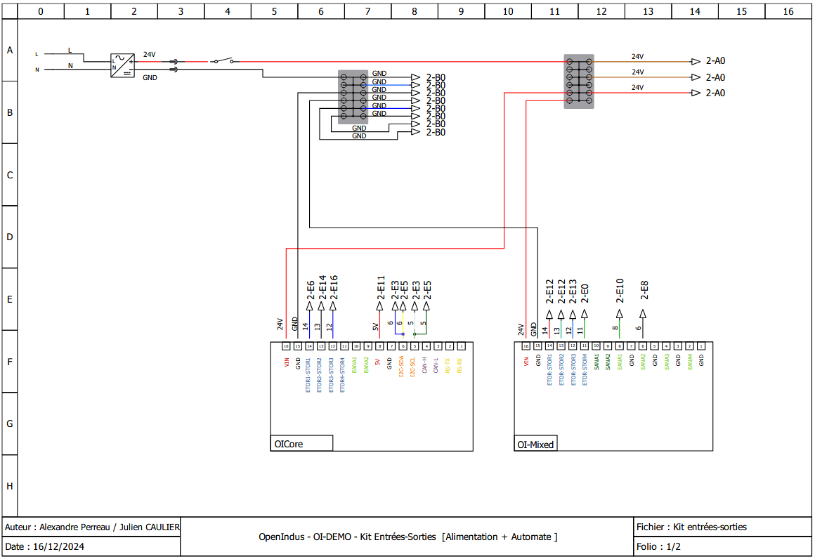
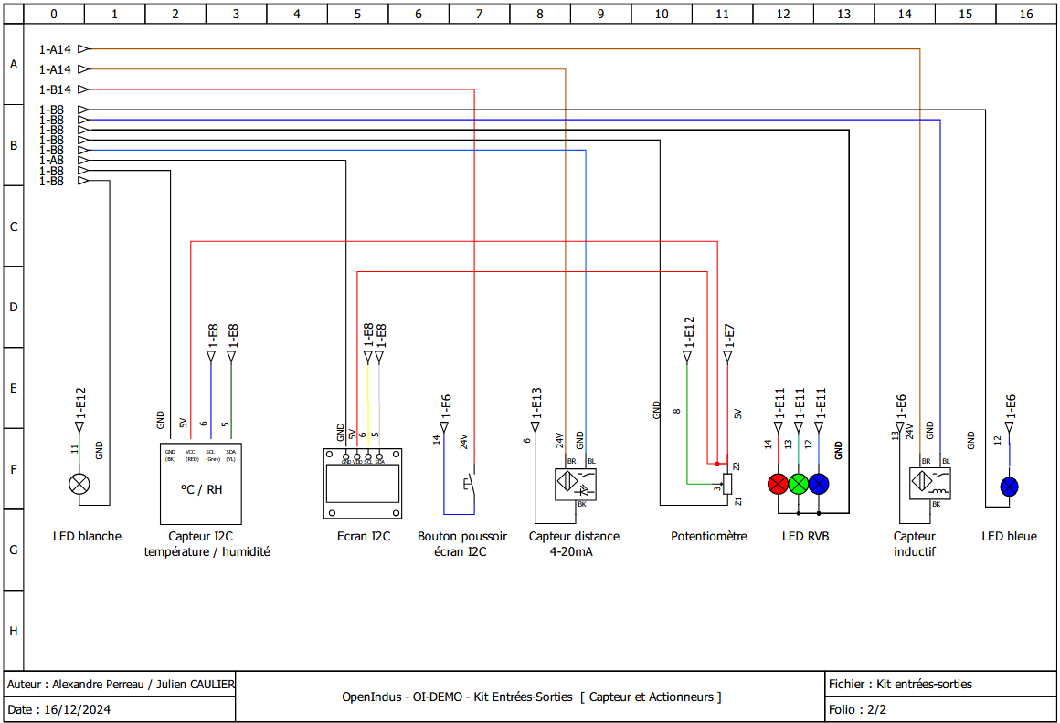
Wiring diagrams
The Demo IO kit is wired as described in the diagrams below. By following the connections you can see which pins are used for each sensor or actuator. These pin identifiers will be used throughout the code examples.
3. Develop your own project
Introduction to OpenIndus IDE
OpenIndus projects are developed with Visual Studio Code and the OpenIndus extension. The extension handles project creation, compilation, and flashing directly from the editor.
Refer to the Environment Installation guide to set up your workspace if you have not done so yet.
Introduction to OpenIndus modules programming
Once the extension is installed and your workspace is set up, you can start writing code for the Demo Input/Output kit.
In the extension, launch “Start a new project”:
Select OI Core
Select the parent folder of the project
Enter the project name (e.g.
OpenIndus_Demo_IO)Select “Master” as the device type
Choose to use Arduino libraries
Select the last available version of the OpenIndus library
Note
In the newly created project, edit the main/main.cpp file to implement the I/O control logic.
All code examples in this section are excerpts from main/main.cpp. The full source code is
available at the end of this page.
The OI-Demo Input/Output kit uses two OpenIndus modules on a shared OI-Rail bus:
OI-Core — the master controller that manages digital I/O and orchestrates the system
OI-Mixed — provides analog inputs, analog outputs, and digital outputs with PWM capability
In code, each module is declared as a global object. The OpenIndus extension can generate these declarations automatically by scanning the OI-Rail:
#include "OpenIndus.h"
#include "Arduino.h"

// Master device
OICore core;

// Slave devices
OIMixed mixed1;
Third-party Adafruit libraries are also required to drive the I²C display and the temperature/humidity sensor. Include them at the top of the file:
// Peripherals libs
#include "Adafruit_I2CDevice.h"
#include "Adafruit_GFX.h"
#include "Adafruit_SSD1306.h"
#include "Adafruit_Sensor.h"
#include "Fonts/FreeMono9pt7b.h"
#include "Adafruit_AM2320.h"
Complete example project
This section covers the code of the example project in detail, explaining the structure and the role of each function. The full source code is available at the end of this page.
Project structure
The project is organized around the following functions:
Function |
Role |
|---|---|
|
Hardware initialization: serial, display, sensor, analog inputs, PWM outputs, interrupts, and FreeRTOS tasks |
|
Arduino main loop: cycles through three display modes (temperature, humidity, distance) every 100 ms |
|
ISR: increments |
|
ISR: mirrors the inductive sensor state (OI-Core DIN_2) directly onto the blue LED output |
|
Helper: reads temperature from the AM2320 sensor and refreshes the OLED display |
|
Helper: reads humidity from the AM2320 sensor and refreshes the OLED display |
|
Helper: reads the |
|
FreeRTOS task: continuously acquires distance from the 4-20 mA proximity sensor, computes the median, and adjusts the white LED brightness |
|
FreeRTOS task: continuously reads the potentiometer and maps its value to RGB LED colors |
Source code details
Global variables and constants
// Declarations for button debounce function
unsigned long lastDebounceTime;
bool debounceexpired = true;
#define DEBOUNCEDELAY   200

// Declarations for PWM : RGB led and white led
#define PWM_MAX_VAL     16384 // 14 bits resolution

// Declarations for LCD display
#define SCREEN_WIDTH    128 // OLED display width, in pixels
#define SCREEN_HEIGHT   64  // OLED display height, in pixels
#define OLED_RESET      -1  // Reset pin # (or -1 if sharing Arduino reset pin)
#define SCREEN_ADDRESS  0x3D ///< 0x3D for 128x64, 0x3C for 128x32

// declare LCD display
Adafruit_SSD1306 display(SCREEN_WIDTH, SCREEN_HEIGHT, &Wire, OLED_RESET);
// declare humidity and temperature sensor
Adafruit_AM2320 th_sensor = Adafruit_AM2320();

// Variable that stores the current display mode
int display_mode = 0;
// Global variable for the proximity sensor computed distance
float meandistance;
display_modeis an integer cycling between 0, 1 and 2; it is written from the interrupt handlerdisplaymodechange()and read fromloop().meandistanceis a global variable shared between themeasuredistance()FreeRTOS task (writer) and bothdisplaydistance()andmeasuredistance()(readers). Declaring it globally avoids passing pointers between tasks.PWM_MAX_VALreflects the 14-bit resolution of the OI-Mixed PWM outputs: the maximum duty cycle value is $2^{14} = 16384$.DEBOUNCEDELAYdefines the minimum time in milliseconds between two accepted button presses, to filter out electrical contact bounces.
Interrupt handlers
displaymodechange()void displaymodechange(void*) { // if debounce time is expired if( (millis() - lastDebounceTime) >= DEBOUNCEDELAY) { // we can enable again new event debounceexpired = true; } // if debounce time is expired, we can accept a new button event if (debounceexpired == true) { // save timestamp of event lastDebounceTime = millis(); // reset debounceexpired flag debounceexpired = false; // update display mode display_mode++; if (display_mode >= 3) { display_mode = 0; } } }
displaymodechange()is called on every rising edge of the push button connected to OI-Core[DIN_1]. Its role is to advance thedisplay_modevariable so that theloop()function switches what is shown on the OLED.Mechanical buttons produce electrical bounces that can trigger multiple unwanted detections within a single physical press. The software debounce implemented here works as follows:
On the first rising edge, the current timestamp (
millis()) is stored inlastDebounceTimeanddebounceexpiredis set tofalse.Any subsequent rising edge that arrives within
DEBOUNCEDELAYms is silently ignored.Once
DEBOUNCEDELAYms have elapsed,debounceexpiredis set back totrueand the next rising edge will be treated as a new valid event.
blue_led()void blue_led(void*) { static int inductive_sensor; inductive_sensor = core.digitalRead(DIN_2); if (inductive_sensor == 1) { core.digitalWrite(DOUT_3, HIGH); } else { core.digitalWrite(DOUT_3, LOW); } }
blue_led()is called on every state change of the inductive sensor connected to OI-Core[DIN_2] (CHANGE_MODEinterrupt). It immediately mirrors the sensor state onto the blue LED output OI-Core[DOUT_3]: the LED is ON when a metal object is detected, and OFF otherwise.ISRs must be kept as short as possible. This function performs only a single digital read and a single digital write, with no blocking calls.
Display helper functions
These three functions are called from
loop()and each one refreshes the entire OLED screen with a different measurement.displaytemperature()void displaytemperature(void) { display.clearDisplay(); display.setTextSize(1); display.setTextColor(WHITE); display.setCursor(0,25); display.println(F("Temperature: ")); display.setCursor(25,45); display.print(th_sensor.readTemperature(), 2); display.println(F(" °C")); display.display(); }
The AM2320 sensor is queried each time the function is called with
th_sensor.readTemperature(), which returns a floating-point value in degrees Celsius. The result is displayed with two decimal places.display.clearDisplay()erases the framebuffer first, then all drawing calls build the new content, anddisplay.display()pushes the framebuffer to the physical screen in one shot to avoid flickering.displayhumidity()void displayhumidity(void) { display.clearDisplay(); display.setTextSize(1); display.setTextColor(WHITE); display.setCursor(15,25); display.println(F("Humidite: ")); display.setCursor(25,45); display.print(th_sensor.readHumidity(), 2); display.println(F(" %")); display.display(); }
Identical in structure to
displaytemperature(), this function queriesth_sensor.readHumidity()instead, which returns the relative humidity as a percentage.displaydistance()void displaydistance(void) { display.clearDisplay(); display.setTextSize(1); display.setTextColor(WHITE); display.setCursor(15,25); display.println(F("Distance: ")); // meandistance is computed periodically in measuredistance() if (meandistance <= 10) { display.setCursor(25,45); display.println(F(" < 10 mm")); meandistance = 10; } else if (meandistance >= 100) { display.setCursor(25,45); display.println(F(" > 100 mm")); meandistance = 100; } else { display.setCursor(25,45); display.print(meandistance, 2); display.println(F(" mm")); } display.display(); }
Unlike the two previous helpers,
displaydistance()does not perform a sensor read itself. Instead it reads themeandistanceglobal variable, which is continuously updated by themeasuredistance()FreeRTOS task running in the background.The proximity sensor’s guaranteed measurement range is 10 mm to 100 mm. Values outside this range are shown as
< 10 mmor> 100 mmto make it clear to the user that the sensor has reached its physical limit.
FreeRTOS tasks
measuredistance()void measuredistance(void*) { int nSAMPLES = 10; std::vector<float> rdist; rdist.resize(nSAMPLES); // infinite loop for capturing distance while(1) { // acquire multiple values of distance for(int i=0; i < nSAMPLES; i++) { rdist[i] = 5.625 * mixed1.analogReadMilliAmp(AIN_2) - 12.5; delay(5); } // compute median distance over multiple samples std::sort(rdist.begin(), rdist.end()); size_t size = rdist.size(); if (size % 2 == 0) { meandistance = (rdist[size / 2 - 1] + rdist[size / 2]) / 2.0; } else { meandistance = rdist[size / 2]; } // clamp to sensor range if (meandistance > 100) { meandistance = 100; } else if (meandistance < 10) { meandistance = 10; } // remap distance to PWM range (inverted: closer = brighter) int pwmwhiteled = map(meandistance, 10, 100, PWM_MAX_VAL, 0); mixed1.setPWMDutyCycle(DOUT_4, pwmwhiteled); delay(5); } }
This task runs in an infinite loop at priority 1 and is responsible for three things: acquiring raw distance samples, filtering them, and adjusting the white LED brightness.
Acquisition — the proximity sensor outputs a 4-20 mA current proportional to distance.
analogReadMilliAmp(AIN_2)returns the current in milliamps. The linear formula converts milliamps to millimeters:rdist[i] = 5.625 * mixed1.analogReadMilliAmp(AIN_2) - 12.5;
Ten samples are collected with a 5 ms pause between each, for a total acquisition window of about 50 ms.
Filtering — a median filter is used instead of a simple average because it is insensitive to occasional outlier readings from the sensor. The median is the central value of a sorted dataset: 50 % of values are below it and 50 % are above it. To compute the median, the samples are sorted and the middle element is selected:
std::sort(rdist.begin(), rdist.end()); size_t size = rdist.size(); if (size % 2 == 0) meandistance = (rdist[size / 2 - 1] + rdist[size / 2]) / 2.0; else meandistance = rdist[size / 2];
Clamping and PWM update — the filtered value is clamped to the sensor’s guaranteed range [10, 100] mm, then remapped to a PWM duty cycle with
map():int pwmwhiteled = map(meandistance, 10, 100, PWM_MAX_VAL, 0); mixed1.setPWMDutyCycle(DOUT_4, pwmwhiteled);
The mapping is inverted: a distance of 10 mm (closest) produces the maximum duty cycle (full brightness), while 100 mm (farthest) produces 0 (LED off).
map()is a utility that linearly converts a value from one range to another.rgb_pot()void rgb_pot(void*) { int currentColorValueRed = 0; int currentColorValueGreen = 0; int currentColorValueBlue = 0; int potPinValue; while(1) { potPinValue = map(mixed1.analogRead(AIN_1), 0, 4096, 0, PWM_MAX_VAL); if (potPinValue <= (PWM_MAX_VAL * 1/6)) { currentColorValueRed = PWM_MAX_VAL; currentColorValueGreen = potPinValue * 6; currentColorValueBlue = 0; } if ((potPinValue > (PWM_MAX_VAL * 1/6)) && (potPinValue <= (PWM_MAX_VAL * 2/6))) { currentColorValueRed = PWM_MAX_VAL - (potPinValue - (PWM_MAX_VAL * 1/6)) * 6; currentColorValueGreen = PWM_MAX_VAL; currentColorValueBlue = 0; } if ((potPinValue > (PWM_MAX_VAL * 2/6)) && (potPinValue <= (PWM_MAX_VAL * 3/6))) { currentColorValueRed = 0; currentColorValueGreen = PWM_MAX_VAL; currentColorValueBlue = (potPinValue - (PWM_MAX_VAL * 2/6)) * 6; } if ((potPinValue > (PWM_MAX_VAL * 3/6)) && (potPinValue <= (PWM_MAX_VAL * 4/6))) { currentColorValueRed = 0; currentColorValueGreen = PWM_MAX_VAL - (potPinValue - (PWM_MAX_VAL * 3/6)) * 6; currentColorValueBlue = PWM_MAX_VAL; } if ((potPinValue > (PWM_MAX_VAL * 4/6)) && (potPinValue <= (PWM_MAX_VAL * 5/6))) { currentColorValueRed = (potPinValue - (PWM_MAX_VAL * 4/6)) * 6; currentColorValueGreen = 0; currentColorValueBlue = PWM_MAX_VAL; } if ((potPinValue > (PWM_MAX_VAL * 5/6)) && (potPinValue <= (PWM_MAX_VAL * 6/6))) { currentColorValueRed = PWM_MAX_VAL; currentColorValueGreen = 0; currentColorValueBlue = PWM_MAX_VAL - (potPinValue - (PWM_MAX_VAL * 5/6)) * 6; } mixed1.setPWMDutyCycle(DOUT_1, currentColorValueRed); mixed1.setPWMDutyCycle(DOUT_2, currentColorValueGreen); mixed1.setPWMDutyCycle(DOUT_3, currentColorValueBlue); delay(50); } }
rgb_pot()runs in an infinite loop at priority 2 (higher thanmeasuredistance()) and maps the potentiometer position to an RGB color.The potentiometer is connected to OI-Mixed[AIN_1] in voltage mode.
analogRead()returns a raw ADC value in the range [0, 4096]. This value is first remapped to the PWM range [0,PWM_MAX_VAL] usingmap():potPinValue = map(mixed1.analogRead(AIN_1), 0, 4096, 0, PWM_MAX_VAL);
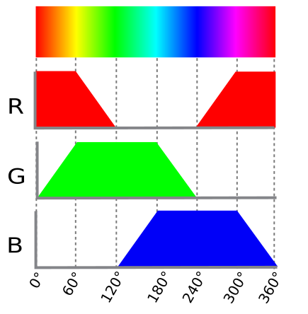
The full range is then split into six equal segments. In each segment one color component is at its maximum, one is ramping up or down, and one is off. This produces a continuous color wheel: red → yellow → green → cyan → blue → magenta → red.
Each
setPWMDutyCycle()call updates the corresponding LED channel output on the OI-Mixed module instantly. A 50 ms delay keeps the loop from running faster than necessary and yields CPU time to lower-priority tasks.
setup()
setup()is executed once at power-on and is responsible for all hardware initialization before the main loop starts.Serial.begin(115200);
Opens the USB serial port at 115200 baud. Debug messages will appear in any terminal configured for 115200 baud, 8-N-1.
if(!display.begin(SSD1306_SWITCHCAPVCC, 0x3C)) { Serial.println(F("SSD1306 allocation failed")); for(;;); // Don't proceed, loop forever }
Initializes the SSD1306 OLED display.
SSD1306_SWITCHCAPVCCinstructs the driver IC to generate the display voltage internally from the 3.3 V supply. If initialization fails (e.g. wrong I²C address or wiring issue), the program halts with an error message rather than silently continuing with a broken display.display.setFont((const GFXfont *)&FreeMono9pt7b); display.display(); delay(2000); display.clearDisplay();
Sets the font and shows the Adafruit splash screen for 2 seconds, then clears the buffer ready for the application content.
// set AIN_1 to analog mode with voltage measure (potentiometer) mixed1.analogInputMode(AIN_1, AIN_MODE_VOLTAGE); mixed1.analogInputVoltageRange(AIN_1, AIN_VOLTAGE_RANGE_0_5V12); // set AIN_2 to analog mode with current measure (proximity sensor) mixed1.analogInputMode(AIN_2, AIN_MODE_CURRENT);
Configures the two analog inputs:
OI-Mixed[AIN_1] is wired to the potentiometer (voltage signal). The range is set to 0–5.12 V to match the 5 V supply of the potentiometer and use the full ADC resolution.
OI-Mixed[AIN_2] is wired to the 4-20 mA proximity sensor (current signal).
// set PWM outputs for RGB led mixed1.outputMode(DOUT_1, DOUT_MODE_PWM); // Red mixed1.outputMode(DOUT_2, DOUT_MODE_PWM); // Green mixed1.outputMode(DOUT_3, DOUT_MODE_PWM); // Blue mixed1.setPWMFrequency(DOUT_1, 100); mixed1.setPWMFrequency(DOUT_2, 100); mixed1.setPWMFrequency(DOUT_3, 100); mixed1.setPWMDutyCycle(DOUT_1, 0); mixed1.setPWMDutyCycle(DOUT_2, 0); mixed1.setPWMDutyCycle(DOUT_3, 0);
Switches outputs DOUT_1, DOUT_2, and DOUT_3 to PWM mode, sets the PWM frequency to 100 Hz (fast enough to avoid visible flicker), and initializes all channels to 0 so the RGB LED starts off.
outputMode(pin, DOUT_MODE_PWM) — switches a digital output from its default on/off mode to PWM mode.
setPWMFrequency(pin, Hz) — sets the PWM carrier frequency in hertz.
setPWMDutyCycle(pin, value) — sets the duty cycle from 0 (always off) to
PWM_MAX_VAL(always on).// set PWM outputs for white led mixed1.outputMode(DOUT_4, DOUT_MODE_PWM); mixed1.setPWMFrequency(DOUT_4, 100); mixed1.setPWMDutyCycle(DOUT_4, 0);
The same configuration is applied to DOUT_4, which drives the white LED whose brightness is modulated by the proximity sensor distance.
core.attachInterrupt(DIN_1, displaymodechange, RISING_MODE, NULL); core.attachInterrupt(DIN_2, blue_led, CHANGE_MODE, NULL);
Registers two interrupt callbacks on the OI-Core digital inputs:
DIN_1 / RISING_MODE —
displaymodechange()is called once on each rising edge of the push button signal (button pressed).DIN_2 / CHANGE_MODE —
blue_led()is called on every state change of the inductive sensor output (both detection and release events).
xTaskCreate(measuredistance, "Measure distance", 20000, NULL, 1, NULL); xTaskCreate(rgb_pot, "rgb_pot", 10000, NULL, 2, NULL);
Spawns the two background tasks using the FreeRTOS API. Both tasks run concurrently alongside
loop().rgb_potis given a higher priority (2) thanmeasuredistance(1) so that the color response to the potentiometer feels immediate.xTaskCreate(function, name, stack size, parameter, priority, handle) — creates a FreeRTOS task. The stack size is given in bytes; the values here are generous to accommodate the
std::vectorandstd::sortcalls insidemeasuredistance.Serial.println(F("Setup done."));
A confirmation message printed when all initialization steps have completed successfully.
loop()
void loop(void) { switch(display_mode) { case 0: default: displaytemperature(); break; case 1: displayhumidity(); break; case 2: displaydistance(); break; } delay(100); }
loop()is called repeatedly by the Arduino runtime. Its only responsibility is to refresh the OLED display with whichever measurement corresponds to the currentdisplay_mode:Mode 0 — temperature
Mode 1 — humidity
Mode 2 — distance
display_modeis incremented by thedisplaymodechange()interrupt handler each time the push button is pressed, cycling back to 0 after mode 2.The
delay(100)at the end of each iteration is important: it yields the CPU to the FreeRTOS scheduler so thatmeasuredistance()andrgb_pot()get regular execution time. Omitting it would starve the background tasks.
Source code (full)
#include "OpenIndus.h"
#include "Arduino.h"
// Peripherals libs
#include "Adafruit_I2CDevice.h"
#include "Adafruit_GFX.h"
#include "Adafruit_SSD1306.h"
#include "Adafruit_Sensor.h"
#include "Fonts/FreeMono9pt7b.h"
#include "Adafruit_AM2320.h"
// First, init the master device
OICore core;
// Then add slaves devices here :
OIMixed mixed1;
// Declarations for button debounce function
hw_timer_t * timer = NULL;
unsigned long lastDebounceTime;
bool debounceexpired = true;
#define DEBOUNCEDELAY 200
// Declarations for PWM : RGB led and white led
#define PWM_MAX_VAL 16384 // 14 bits resolution
// Declarations for LCD display
#define SCREEN_WIDTH 128 // OLED display width, in pixels
#define SCREEN_HEIGHT 64 // OLED display height, in pixels
// Declaration for an SSD1306 display connected to I2C (SDA, SCL pins)
#define OLED_RESET -1 // Reset pin # (or -1 if sharing Arduino reset pin)
#define SCREEN_ADDRESS 0x3D ///< See datasheet for Address; 0x3D for 128x64, 0x3C for 128x32
// declare LCD display
Adafruit_SSD1306 display(SCREEN_WIDTH, SCREEN_HEIGHT, &Wire, OLED_RESET);
// declare humidity and temperature sensor
Adafruit_AM2320 th_sensor = Adafruit_AM2320();
// Variable that store current mode
int display_mode = 0;
// Declare globle variable for proximity sensor
float meandistance;
void displaymodechange(void*)
{
// if debounce time is expired
if( (millis() - lastDebounceTime) >= DEBOUNCEDELAY)
{
// we can enable again new event
debounceexpired = true;
}
// if debounce time is expired, we can accept a new button event
if (debounceexpired == true)
{
// same timestamp of event
lastDebounceTime = millis();
// reset debounceexpired flag
debounceexpired = false;
// update display mode
display_mode++;
if (display_mode >= 3)
{
display_mode = 0;
}
}
}
void blue_led(void*)
{
    static int inductive_sensor;
    inductive_sensor = core.digitalRead(DIN_2);
    if (inductive_sensor == 1)
    {
        core.digitalWrite(DOUT_3, HIGH);
    }
    else
    {
        core.digitalWrite(DOUT_3, LOW);
    }
}
void displaytemperature(void)
{
    display.clearDisplay();
    display.setTextSize(1);
    display.setTextColor(WHITE);
    display.setCursor(0,25);
    display.println(F("Temperature: "));
    display.setCursor(25,45);
    display.print(th_sensor.readTemperature(), 2);
    display.println(F(" °C"));
    display.display();
}
void displayhumidity(void)
{
    display.clearDisplay();
    display.setTextSize(1);
    display.setTextColor(WHITE);
    display.setCursor(15,25);
    display.println(F("Humidite: "));
    display.setCursor(25,45);
    display.print(th_sensor.readHumidity(), 2);
    display.println(F(" %"));
    display.display();
}
void measuredistance(void*)
{
int nSAMPLES = 10;
std::vector<float> rdist;
rdist.resize(nSAMPLES);
// infinite loop for capturing distance
while(1)
{
// acquire multiple values of distance
for(int i=0; i < nSAMPLES; i++)
{
rdist[i] = 5.625 * mixed1.analogReadMilliAmp(AIN_2) - 12.5;
delay(5);
}
// compute mean distance over multiple samples
std::sort(rdist.begin(), rdist.end());
size_t size = rdist.size();
if (size % 2 == 0)
{
// store result in global variable, may be use in displaydistance()
meandistance = (rdist[size / 2 - 1] + rdist[size / 2]) / 2.0;
}
else
{
// store result in global variable, may be use in displaydistance()
meandistance = rdist[size / 2];
}
// set out of range value to 0-100
if (meandistance > 100)
{
meandistance = 100;
}
else if (meandistance < 10)
{
meandistance = 10;
}
// PWM duty cycle resolution is 2^14 . remapping is reversed to increase luminosity while decreasing distance (led is off when distance is > 100 mm)
// remap meandistance to 0-16384 pwm range
int pwmwhiteled = map(meandistance, 10, 100, PWM_MAX_VAL, 0);
// adjust white led intensity
mixed1.setPWMDutyCycle(DOUT_4, pwmwhiteled);
delay(5);
}
}
void displaydistance(void)
{
    display.clearDisplay();
    display.setTextSize(1);
    display.setTextColor(WHITE);
    display.setCursor(15,25);

    display.println(F("Distance: "));

    // meandistance is computed periodically in measuredistance()
    if (meandistance <= 10)
    {
        display.setCursor(25,45);
        display.println(F(" < 10 mm"));
        meandistance = 10;
    }
    else if (meandistance >= 100)
    {
        display.setCursor(25,45);
        display.println(F(" > 100 mm"));
        meandistance = 100;
    }
    else
    {
        display.setCursor(25,45);
        display.print(meandistance, 2);
        display.println(F(" mm"));
    }
    display.display();
}
void rgb_pot(void*)
{
// Values for each pin of the RGB LED.
int currentColorValueRed = 0;
int currentColorValueGreen = 0 ;
int currentColorValueBlue = 0 ;
int potPinValue;
while(1)
{
// read potentiometer value (0 - 4096)
// and convert it to a RGB range (0 - PWM_MAX_VAL).
potPinValue = map(mixed1.analogRead(AIN_1), 0, 4096, 0, PWM_MAX_VAL);
// Explanation of the code can be found on this link :
// https://electronics.stackexchange.com/questions/240185/controlling-color-and-brightness-of-rgb-led-strip-using-one-potentiometer
// Note: 1/6th of 255 is 42.5
if (potPinValue <= (PWM_MAX_VAL * 1/6))
{
currentColorValueRed = PWM_MAX_VAL;
currentColorValueGreen = potPinValue * 6;
currentColorValueBlue = 0;
}
if ((potPinValue > (PWM_MAX_VAL * 1/6)) && (potPinValue <= (PWM_MAX_VAL * 2/6)))
{
currentColorValueRed = PWM_MAX_VAL - (potPinValue - (PWM_MAX_VAL * 1/6)) * 6;
currentColorValueGreen = PWM_MAX_VAL;
currentColorValueBlue = 0;
}
if ((potPinValue > (PWM_MAX_VAL * 2/6)) && (potPinValue <= (PWM_MAX_VAL * 3/6)))
{
currentColorValueRed = 0;
currentColorValueGreen = PWM_MAX_VAL;
currentColorValueBlue = (potPinValue - (PWM_MAX_VAL * 2/6)) * 6;
}
if ((potPinValue > (PWM_MAX_VAL * 3/6)) && (potPinValue <= (PWM_MAX_VAL * 4/6)))
{
currentColorValueRed = 0;
currentColorValueGreen = PWM_MAX_VAL - (potPinValue - (PWM_MAX_VAL * 3/6)) * 6;
currentColorValueBlue = PWM_MAX_VAL;
}
if ((potPinValue > (PWM_MAX_VAL* 4/6)) && (potPinValue <= (PWM_MAX_VAL* 5/6)))
{
currentColorValueRed = (potPinValue - (PWM_MAX_VAL* 4/6)) * 6;
currentColorValueGreen = 0;
currentColorValueBlue = PWM_MAX_VAL;
}
if ((potPinValue > (PWM_MAX_VAL* 5/6)) && (potPinValue <= (PWM_MAX_VAL* 6/6)))
{
currentColorValueRed = PWM_MAX_VAL;
currentColorValueGreen = 0;
currentColorValueBlue = PWM_MAX_VAL - (potPinValue - (PWM_MAX_VAL* 5/6)) * 6;
}
// adjust RGB colors following measured potentiometer value
mixed1.setPWMDutyCycle(DOUT_1, currentColorValueRed);
mixed1.setPWMDutyCycle(DOUT_2, currentColorValueGreen);
mixed1.setPWMDutyCycle(DOUT_3, currentColorValueBlue);
delay(50);
}
}
void setup(void)
{
Serial.begin(115200);
// SSD1306_SWITCHCAPVCC = generate display voltage from 3.3V internally
if(!display.begin(SSD1306_SWITCHCAPVCC, 0x3C))
{
    Serial.println(F("SSD1306 allocation failed"));
    for(;;); // Don't proceed, loop forever
}
// Show initial display buffer contents on the screen --
// the library initializes this with an Adafruit splash screen.
display.setFont((const GFXfont *)&FreeMono9pt7b);
display.display();
delay(2000); // Pause for 2 seconds
// Clear the buffer
display.clearDisplay();
// set AIN_1 to analog mode with voltage measure (potentiometer)
mixed1.analogInputMode(AIN_1, AIN_MODE_VOLTAGE);
mixed1.analogInputVoltageRange(AIN_1, AIN_VOLTAGE_RANGE_0_5V12 );
// set AIN_2 to analog mode with current measure (proximity sensor)
mixed1.analogInputMode(AIN_2, AIN_MODE_CURRENT);
// set PWM outputs for RGB led
mixed1.outputMode(DOUT_1, DOUT_MODE_PWM ); // Red Led
mixed1.outputMode(DOUT_2, DOUT_MODE_PWM ); // Green led
mixed1.outputMode(DOUT_3, DOUT_MODE_PWM ); // Blue led
// set PWM frequency
mixed1.setPWMFrequency(DOUT_1, 100);
mixed1.setPWMFrequency(DOUT_2, 100);
mixed1.setPWMFrequency(DOUT_3, 100);
// set all RGB leds off
mixed1.setPWMDutyCycle(DOUT_1, 0);
mixed1.setPWMDutyCycle(DOUT_2, 0);
mixed1.setPWMDutyCycle(DOUT_3, 0);
// set PWM outputs for white led
mixed1.outputMode(DOUT_4, DOUT_MODE_PWM );
// set PWM frequency
mixed1.setPWMFrequency(DOUT_4, 100);
// set white led off
mixed1.setPWMDutyCycle(DOUT_4, 0);
core.attachInterrupt(DIN_1, displaymodechange, RISING_MODE, NULL );
core.attachInterrupt(DIN_2, blue_led, CHANGE_MODE, NULL );
xTaskCreate(measuredistance, "Measure distance", 20000, NULL, 1, NULL);
xTaskCreate(rgb_pot, "rgb_pot", 10000, NULL, 2, NULL);
Serial.println(F("Setup done."));
}
void loop(void)
{
switch(display_mode)
{
case 0 :
default:
displaytemperature();
break;
case 1 :
displayhumidity();
break;
case 2 :
displaydistance();
break;
}
delay(100);
}