OI-DEMO Input/Output
Goals
Introducing Environment Installation
Read values from I²C sensor
Diplay info on I²C display
Manage input events with tasks and interrupts
Read analog voltages
Drive an RGB Led with PWM outputs
Drive Leds with outputs
Requirements
Visual Studio Code
VSCode Openindus extension (Recommanded)
SiliconLabs USB Driver installed (CP2102N - USB<->UART)
Understanding Start coding chapter
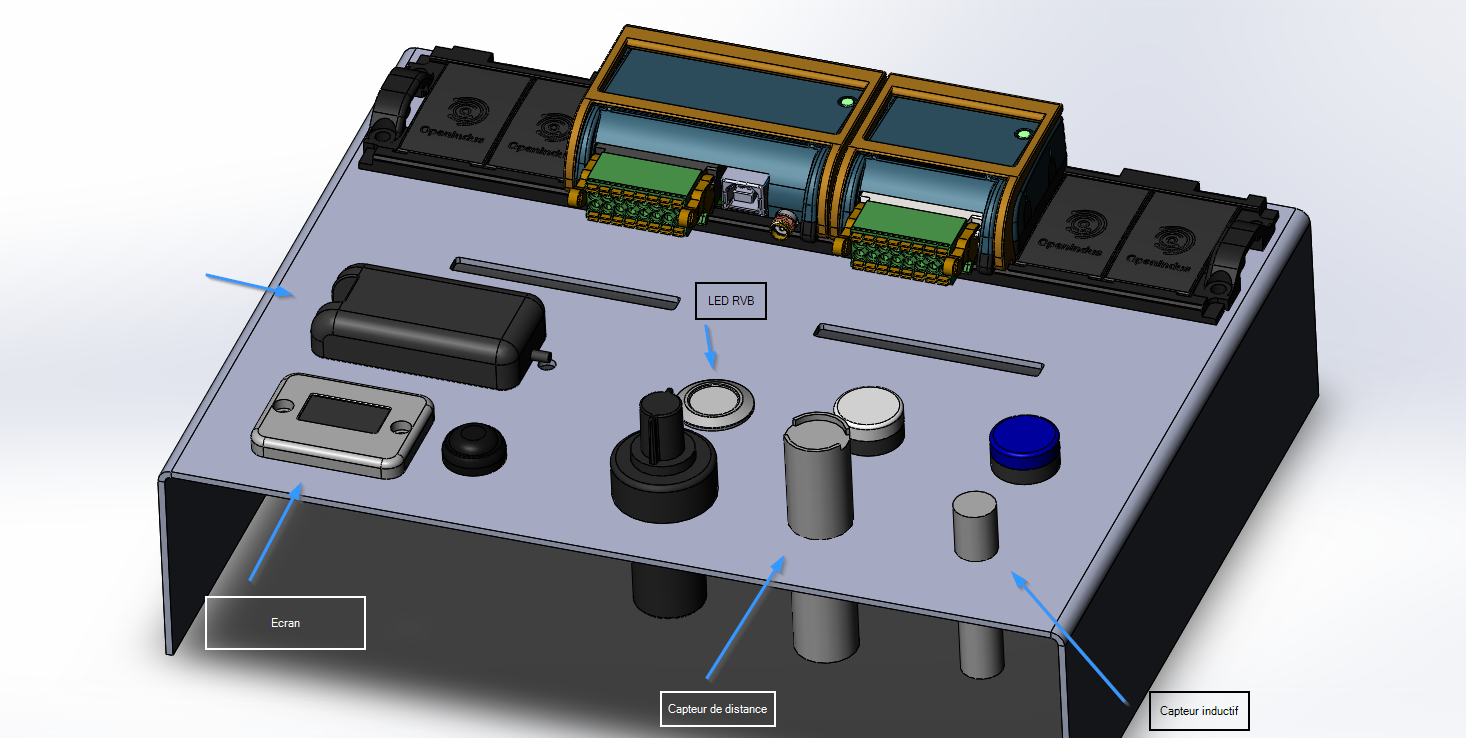
Description
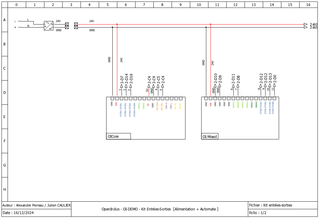
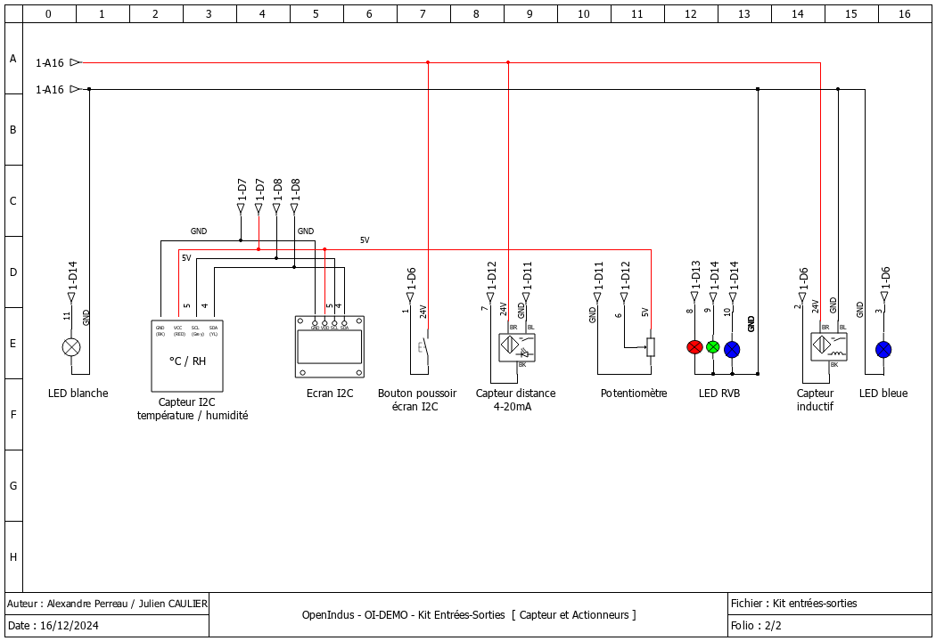
Wiring diagrams
Demo IO kit is wired as described below :
Source code details
Libraries declaration
First, include all libraries needed for each sensor or output devices.
// Peripherals libs
#include "Adafruit_I2CDevice.h"
#include "Adafruit_GFX.h"
#include "Adafruit_SSD1306.h"
#include "Adafruit_Sensor.h"
#include "Fonts/FreeMono9pt7b.h"
#include "Adafruit_AM2320.h"
OI Modules instances
// First, init the master device
OICore core;

// Then add slaves devices here :
OIMixed mixed1;
These lines should be automatically created while using OpenIndus extension. It creates instances for each OI Module found on the OI-Rail.
Variables / constants declaration
// Declarations for button debounce function
hw_timer_t * timer = NULL;
unsigned long lastDebounceTime;
bool debounceexpired = true;
#define DEBOUNCEDELAY   200
For the button debounce function, we need a timer (hw_timer_t) and variables to use it. See below.
// Declarations for PWM : RGB led and white led
#define PWM_MAX_VAL     16384 // 14 bits resolution
PWM_MAX_VAL define the max value for PWM functions (RGB and Led outputs)
// Declarations for LCD display
#define SCREEN_WIDTH    128 // OLED display width, in pixels
#define SCREEN_HEIGHT   64 // OLED display height, in pixels
// Declaration for an SSD1306 display connected to I2C (SDA, SCL pins)
#define OLED_RESET      -1 // Reset pin # (or -1 if sharing Arduino reset pin)
#define SCREEN_ADDRESS  0x3D ///< See datasheet for Address; 0x3D for 128x64, 0x3C for 128x32

// declare LCD display
Adafruit_SSD1306 display(SCREEN_WIDTH, SCREEN_HEIGHT, &Wire, OLED_RESET);
// declare humidity and temperature sensor
Adafruit_AM2320 th_sensor = Adafruit_AM2320();
// Declare semaphore
SemaphoreHandle_t xMutex = NULL;
Constants declarations are about size of the LCD Display. For SCREEN_ADDRESS, please refer to LCD Display datasheet.
// declare humidity and temperature sensor
Adafruit_AM2320 th_sensor = Adafruit_AM2320();
Create an instance of temperature and humidity sensor.
Setup() function
This function is executed once at startup. Initialisations have to be done here.
Serial.begin(115200);
Initialise serial interface (USB) at 115200 bauds. Debug message will be displayed on a terminal software configured à 115200 bauds 8-N-1 (8 bits, Parity Even, 1 stop bit).
// SSD1306_SWITCHCAPVCC = generate display voltage from 3.3V internally
if(!display.begin(SSD1306_SWITCHCAPVCC, 0x3C))
{
    Serial.println(F("SSD1306 allocation failed"));
    for(;;); // Don't proceed, loop forever
}
LCD Display has to generate its own 3.3V, initialise internal register with this setup.
// Show initial display buffer contents on the screen --
// the library initializes this with an Adafruit splash screen.
display.setFont((const GFXfont *)&FreeMono9pt7b);
display.display();
delay(2000); // Pause for 2 seconds
// Clear the buffer
display.clearDisplay();
Set Font to use while displaying text. Then clear screen after Adafruit logo sequence (2 seconds long).
// set AIN_1 to analog mode with voltage measure (potentiometer)
mixed1.analogInputMode(AIN_1, AIN_MODE_VOLTAGE);
mixed1.analogInputVoltageRange(AIN_1, AIN_VOLTAGE_RANGE_0_5V12 );
// set AIN_2 to analog mode with current measure (proximity sensor)
mixed1.analogInputMode(AIN_2, AIN_MODE_CURRENT);
Initialize analog inputs :
OI-Mixed[AIN1] is wired to the potentiometer so we specify this input as an analog voltage mode.
As potentiometer is supply by 5V, OI-Mixed[AIN1] is set to a range from 0 - 5.12V to get full scale resolution of ADC.
OI-Mixed[AIN2] is wired to 4-20mA sensor (proximity sensor), so we specify this input as an current input.
// set PWM outputs for RGB led
mixed1.outputMode(DOUT_1, DOUT_MODE_PWM );   // Red Led
mixed1.outputMode(DOUT_2, DOUT_MODE_PWM );   // Green led
mixed1.outputMode(DOUT_3, DOUT_MODE_PWM );   // Blue led
Set PWM ouputs for RGB LED : OI-Mixed[DOUT_x]. Each led of the RGB LED is driven by a PWM to set luminosity of each color individualy.
// set PWM frequency
mixed1.setPWMFrequency(DOUT_1, 100);
mixed1.setPWMFrequency(DOUT_2, 100);
mixed1.setPWMFrequency(DOUT_3, 100);
Set frequency of each PWM output. For RGB led, 100 Hz will be enough to avoir retinal persistence.
// set all RGB leds off
mixed1.setPWMDutyCycle(DOUT_1, 0);
mixed1.setPWMDutyCycle(DOUT_2, 0);
mixed1.setPWMDutyCycle(DOUT_3, 0);
By default, set cycle to 0 to shutdown RGB leds at startup.
// set PWM outputs for white led
mixed1.outputMode(DOUT_4, DOUT_MODE_PWM );
// set PWM frequency
mixed1.setPWMFrequency(DOUT_4, 100);
// set white led off
mixed1.setPWMDutyCycle(DOUT_4, 0);
Proceed to same configuration for the white Led wired on OI-Mixed[DOUT_4].
core.attachInterrupt(DIN_1, displaymodechange, RISING_MODE, NULL );
This function configures an interrupt : a rising event on OI-Core[DIN_1] will call displaymodechange() function.
core.attachInterrupt(DIN_2, blue_led, CHANGE_MODE, NULL );
This function configures an interrupt : a rising or falling event on OI-Core[DIN_2] will call blue_led() function.
xTaskCreate(measuredistance, "Measure distance", 20000, NULL, 1, NULL);
This function create a task measuredistance() that runs in parallel of Loop() function. Its priority is set to 1.
xTaskCreate(rgb_pot, "rgb_pot", 10000, NULL, 2, NULL);
This function create a task rgb_pot() that runs in parallel of Loop() function. Its priority is set to 2, that is an higher priority than measuredistance().
Serial.println(F("Setup done."));
When everything is initialized, we can send a debug message.
Loop() function
void loop(void)
{

    switch(display_mode)
    {
        case 0 :
        default:
            displaytemperature();
            break;

        case 1 :
            displayhumidity();
            break;

        case 2 :
            displaydistance();
            break;
    }

    delay(100);
}
The main function is looping on the management of the rolling menu that changes display content on each button action. Interrupt function attached to the button event incremets ‘display_mode’ variable.
‘delay(100)’ is strongly recommended in the loop() function to let operating system execute its own task.
Others functions called in Setup() and Loop() functions
displaytemperature()
void displaytemperature(void)
{
    display.clearDisplay();
    display.setTextSize(1);
    display.setTextColor(WHITE);
    display.setCursor(0,25);
    display.println(F("Temperature: "));
    display.setCursor(25,45);
    display.print(th_sensor.readTemperature(), 2);
    display.println(F(" °C"));
    display.display();
}
This function is called periodically in the Loop() function. Temperature is get from sensor and displayed on LCD.
displayhumidity()
void displayhumidity(void)
{
    display.clearDisplay();
    display.setTextSize(1);
    display.setTextColor(WHITE);
    display.setCursor(15,25);
    display.println(F("Humidite: "));
    display.setCursor(25,45);
    display.print(th_sensor.readHumidity(), 2);
    display.println(F(" %"));
    display.display();
}
This function is called periodically in the Loop() function. Humidity is get from sensor and displayed on LCD.
displaydistance()
void displaydistance(void)
{
    display.clearDisplay();
    display.setTextSize(1);
    display.setTextColor(WHITE);
    display.setCursor(15,25);

    display.println(F("Distance: "));

    // meandistance is computed periodically in measuredistance()
    if (meandistance <= 10)
    {
        display.setCursor(25,45);
        display.println(F(" < 10 mm"));
        meandistance = 10;
    }
    else if (meandistance >= 100)
    {
        display.setCursor(25,45);
        display.println(F(" > 100 mm"));
        meandistance = 100;
    }
    else
    {
        display.setCursor(25,45);
        display.print(meandistance, 2);
        display.println(F(" mm"));
    }
    display.display();
}
This function is called periodically in the Loop() function.
meandistance is get from a global variable and displayed on LCD.
meandistance is computed by measuredistance() that is a task dedicated to this measure.
measuredistance()
void measuredistance(void*)
{
    int nSAMPLES = 10;
    std::vector<float> rdist;
    rdist.resize(nSAMPLES);

    // infinite loop for capturing distance
    while(1)
    {
        // acquire multiple values of distance
        for(int i=0; i < nSAMPLES; i++)
        {
            rdist[i] = 5.625 * mixed1.analogReadMilliAmp(AIN_2) - 12.5;
            delay(5);
        }

        // compute mean distance over multiple samples
        std::sort(rdist.begin(), rdist.end());
        size_t size = rdist.size();
        if (size % 2 == 0)
        {
            // store result in global variable, may be use in  displaydistance()
            meandistance =  (rdist[size / 2 - 1] + rdist[size / 2]) / 2.0;
        }
        else
        {
            // store result in global variable, may be use in  displaydistance()
            meandistance = rdist[size / 2];
        }

        // set out of range value to 0-100
        if (meandistance > 100)
        {
            meandistance = 100;
        }
        else if (meandistance < 10)
        {
            meandistance = 10;
        }

        // PWM duty cycle resolution is 2^14 . remapping is reversed to increase luminosity while decreasing distance (led is off when distance is > 100 mm)
        // remap meandistance to 0-16384 pwm range
        int pwmwhiteled = map(meandistance, 10, 100, PWM_MAX_VAL, 0);
        // adjust white led intensity
        mixed1.setPWMDutyCycle(DOUT_4, pwmwhiteled);

        delay(5);
    }
}
This function compute median value of distance over 100 acquisitions in an infinite loop (while(1)).
// acquire multiple values of distance
for(int i=0; i < nSAMPLES; i++)
{
    rdist[i] = 5.625 * mixed1.analogReadMilliAmp(AIN_2) - 12.5;
    delay(5);
}
With this code, a table a 100 values is filled with an analog read of OI-mixed[AIN_2] input. Analog read is converter to millimeter with a formula.
// compute mean distance over multiple samples
std::sort(rdist.begin(), rdist.end());
size_t size = rdist.size();
if (size % 2 == 0)
{
    // store result in global variable, may be use in  displaydistance()
    meandistance =  (rdist[size / 2 - 1] + rdist[size / 2]) / 2.0;
}
else
{
    // store result in global variable, may be use in  displaydistance()
    meandistance = rdist[size / 2];
}
A median value is better than a mean value because it cancels errors from sensor. The median is the value in the middle of a data set, meaning that 50% of data points have a value smaller or equal to the median and 50% of data points have a value higher or equal to the median. To compute the median value, an easy method consist to sort values of a table and read the value in the middle of this table.
// set out of range value to 0-100
if (meandistance > 100)
{
    meandistance = 100;
}
else if (meandistance < 10)
{
    meandistance = 10;
}
Proximity sensor has a measure range given for 10mm to 100 mm. To stay in this range where sensor has garanted measure, we limit value to this range.
// PWM duty cycle resolution is 2^14 . remapping is reversed to increase luminosity while decreasing distance (led is off when distance is > 100 mm)
// remap meandistance to 0-16384 pwm range
int pwmwhiteled = map(meandistance, 10, 100, PWM_MAX_VAL, 0);
// adjust white led intensity
mixed1.setPWMDutyCycle(DOUT_4, pwmwhiteled);

delay(5);
After median value is computed, the white led PWM output is update to adjuste luminosity. The lower distance, the lower luminosity. map() function is useful to convert a range value to an other one. In this code we convert [10-100] range to [16384-0] (PWM_MAX_VAL) range. It allows to convert distance to PWM equivalent value and inverting value.
displaymodechange()
void displaymodechange(void*)
{
    // if debounce time is expired
    if( (millis() - lastDebounceTime) >= DEBOUNCEDELAY)
    {
        // we can enable again new event
        debounceexpired = true;
    }

    // if debounce time is expired, we can accept a new button event
    if (debounceexpired == true)
    {
        // same timestamp of event
        lastDebounceTime = millis();
        // reset debounceexpired flag
        debounceexpired = false;
        // update display mode
        display_mode++;
        if (display_mode >= 3)
        {
            display_mode = 0;
        }
    }
}
displaymodechange() is called on every rising event of push button. This button has to change the value of display_mode variable in order to change value displayed on LCD.
Mechanical buttons make electricals bounces that can cause unwanted multiple detections. To avoid these unwanted detection, we can add a debounce function. This debounce function use millis() (milliseconds elapsed since startup). At the first rising event of button, we store millis() in a variable. Since the debounce time is not elapsed , we do not consider a rising event as a new event.
blue_led()
void blue_led(void*)
{
    static int inductive_sensor;
    inductive_sensor = core.digitalRead(DIN_2);
    if (inductive_sensor == 1)
    {
        core.digitalWrite(DOUT_3, HIGH);
    }
    else
    {
        core.digitalWrite(DOUT_3, LOW);
    }
}
blue_led() is called on every change of magnetic sensor state. This function set blue led ouput (OI-Mixed[DOUT_3]) following inductive sensor output state (OI-Mixed[DIN_2]).
rgb_pot()
void rgb_pot(void*)
{
    // Values for each pin of the RGB LED.
    int currentColorValueRed = 0;
    int currentColorValueGreen = 0 ;
    int currentColorValueBlue = 0 ;
    int potPinValue;

    while(1)
    {
        // read potentiometer value (0 - 4096)
        // and convert it to a RGB range (0 - PWM_MAX_VAL).
        potPinValue = map(mixed1.analogRead(AIN_1), 0, 4096, 0, PWM_MAX_VAL);

        // Explanation of the code can be found on this link :
        // https://electronics.stackexchange.com/questions/240185/controlling-color-and-brightness-of-rgb-led-strip-using-one-potentiometer
        // Note: 1/6th of 255 is 42.5

        if (potPinValue <= (PWM_MAX_VAL * 1/6))
        {
            currentColorValueRed = PWM_MAX_VAL;
            currentColorValueGreen = potPinValue * 6;
            currentColorValueBlue = 0;
        }

        if ((potPinValue > (PWM_MAX_VAL * 1/6)) && (potPinValue <= (PWM_MAX_VAL * 2/6)))
        {
            currentColorValueRed = PWM_MAX_VAL - (potPinValue - (PWM_MAX_VAL * 1/6)) * 6;
            currentColorValueGreen = PWM_MAX_VAL;
            currentColorValueBlue = 0;
        }

        if ((potPinValue > (PWM_MAX_VAL * 2/6)) && (potPinValue <= (PWM_MAX_VAL * 3/6)))
        {
            currentColorValueRed = 0;
            currentColorValueGreen = PWM_MAX_VAL;
            currentColorValueBlue = (potPinValue - (PWM_MAX_VAL * 2/6)) * 6;
        }

        if ((potPinValue > (PWM_MAX_VAL * 3/6)) && (potPinValue <= (PWM_MAX_VAL * 4/6)))
        {
            currentColorValueRed = 0;
            currentColorValueGreen = PWM_MAX_VAL - (potPinValue - (PWM_MAX_VAL * 3/6)) * 6;
            currentColorValueBlue = PWM_MAX_VAL;
        }

        if ((potPinValue > (PWM_MAX_VAL* 4/6)) && (potPinValue <= (PWM_MAX_VAL* 5/6)))
        {
            currentColorValueRed = (potPinValue - (PWM_MAX_VAL* 4/6)) * 6;
            currentColorValueGreen = 0;
            currentColorValueBlue = PWM_MAX_VAL;
        }

        if ((potPinValue > (PWM_MAX_VAL* 5/6)) && (potPinValue <= (PWM_MAX_VAL* 6/6)))
        {
            currentColorValueRed = PWM_MAX_VAL;
            currentColorValueGreen = 0;
            currentColorValueBlue = PWM_MAX_VAL - (potPinValue - (PWM_MAX_VAL* 5/6)) * 6;
        }

        // adjust RGB colors following measured potentiometer value
        mixed1.setPWMDutyCycle(DOUT_1, currentColorValueRed);
        mixed1.setPWMDutyCycle(DOUT_2, currentColorValueGreen);
        mixed1.setPWMDutyCycle(DOUT_3, currentColorValueBlue);
        delay(50);
    }
}
rgb_pot() is a task that run in an infinite loop. This loop update RGB leds color following position of the potentiometer.
potentiometer value is read on OI-Mixed[AIN_1] input. This analog value [0-4096] is converted with map() function into PWM range value [0-16384].
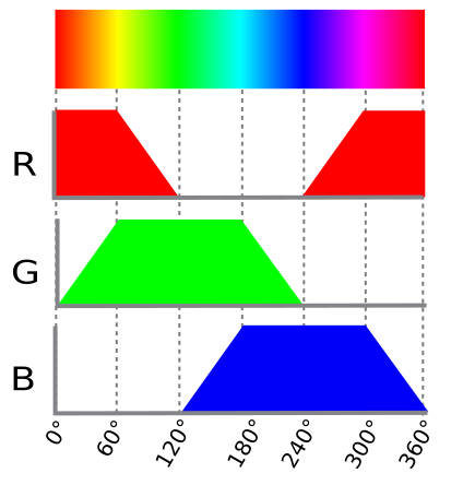
To drive each color (Red, Green and Blue) from a single value, the principle is to convert into six quadrants as presented in the figure below.
potPinValue value is divided in a sixth and then each RGB value is affected to a value as described in the figure.
Source code (full)
#include "OpenIndus.h"
#include "Arduino.h"

// Peripherals libs
#include "Adafruit_I2CDevice.h"
#include "Adafruit_GFX.h"
#include "Adafruit_SSD1306.h"
#include "Adafruit_Sensor.h"
#include "Fonts/FreeMono9pt7b.h"
#include "Adafruit_AM2320.h"

// First, init the master device
OICore core;

// Then add slaves devices here :
OIMixed mixed1;

// Declarations for button debounce function
hw_timer_t * timer = NULL;
unsigned long lastDebounceTime;
bool debounceexpired = true;
#define DEBOUNCEDELAY   200

// Declarations for PWM : RGB led and white led
#define PWM_MAX_VAL     16384 // 14 bits resolution

// Declarations for LCD display
#define SCREEN_WIDTH    128 // OLED display width, in pixels
#define SCREEN_HEIGHT   64 // OLED display height, in pixels
// Declaration for an SSD1306 display connected to I2C (SDA, SCL pins)
#define OLED_RESET      -1 // Reset pin # (or -1 if sharing Arduino reset pin)
#define SCREEN_ADDRESS  0x3D ///< See datasheet for Address; 0x3D for 128x64, 0x3C for 128x32

// declare LCD display
Adafruit_SSD1306 display(SCREEN_WIDTH, SCREEN_HEIGHT, &Wire, OLED_RESET);
// declare humidity and temperature sensor
Adafruit_AM2320 th_sensor = Adafruit_AM2320();

// Variable that store current mode
int display_mode = 0;
// Declare globle variable for proximity sensor
float meandistance;


void displaymodechange(void*)
{
    // if debounce time is expired
    if( (millis() - lastDebounceTime) >= DEBOUNCEDELAY)
    {
        // we can enable again new event
        debounceexpired = true;
    }

    // if debounce time is expired, we can accept a new button event
    if (debounceexpired == true)
    {
        // same timestamp of event
        lastDebounceTime = millis();
        // reset debounceexpired flag
        debounceexpired = false;
        // update display mode
        display_mode++;
        if (display_mode >= 3)
        {
            display_mode = 0;
        }
    }
}


void blue_led(void*)
{
    static int inductive_sensor;
    inductive_sensor = core.digitalRead(DIN_2);
    if (inductive_sensor == 1)
    {
        core.digitalWrite(DOUT_3, HIGH);
    }
    else
    {
        core.digitalWrite(DOUT_3, LOW);
    }
}

void displaytemperature(void)
{
    display.clearDisplay();
    display.setTextSize(1);
    display.setTextColor(WHITE);
    display.setCursor(0,25);
    display.println(F("Temperature: "));
    display.setCursor(25,45);
    display.print(th_sensor.readTemperature(), 2);
    display.println(F(" °C"));
    display.display();
}

void displayhumidity(void)
{
    display.clearDisplay();
    display.setTextSize(1);
    display.setTextColor(WHITE);
    display.setCursor(15,25);
    display.println(F("Humidite: "));
    display.setCursor(25,45);
    display.print(th_sensor.readHumidity(), 2);
    display.println(F(" %"));
    display.display();
}

void measuredistance(void*)
{
    int nSAMPLES = 10;
    std::vector<float> rdist;
    rdist.resize(nSAMPLES);

    // infinite loop for capturing distance
    while(1)
    {
        // acquire multiple values of distance
        for(int i=0; i < nSAMPLES; i++)
        {
            rdist[i] = 5.625 * mixed1.analogReadMilliAmp(AIN_2) - 12.5;
            delay(5);
        }

        // compute mean distance over multiple samples
        std::sort(rdist.begin(), rdist.end());
        size_t size = rdist.size();
        if (size % 2 == 0)
        {
            // store result in global variable, may be use in  displaydistance()
            meandistance =  (rdist[size / 2 - 1] + rdist[size / 2]) / 2.0;
        }
        else
        {
            // store result in global variable, may be use in  displaydistance()
            meandistance = rdist[size / 2];
        }

        // set out of range value to 0-100
        if (meandistance > 100)
        {
            meandistance = 100;
        }
        else if (meandistance < 10)
        {
            meandistance = 10;
        }

        // PWM duty cycle resolution is 2^14 . remapping is reversed to increase luminosity while decreasing distance (led is off when distance is > 100 mm)
        // remap meandistance to 0-16384 pwm range
        int pwmwhiteled = map(meandistance, 10, 100, PWM_MAX_VAL, 0);
        // adjust white led intensity
        mixed1.setPWMDutyCycle(DOUT_4, pwmwhiteled);

        delay(5);
    }
}

void displaydistance(void)
{
    display.clearDisplay();
    display.setTextSize(1);
    display.setTextColor(WHITE);
    display.setCursor(15,25);

    display.println(F("Distance: "));

    // meandistance is computed periodically in measuredistance()
    if (meandistance <= 10)
    {
        display.setCursor(25,45);
        display.println(F(" < 10 mm"));
        meandistance = 10;
    }
    else if (meandistance >= 100)
    {
        display.setCursor(25,45);
        display.println(F(" > 100 mm"));
        meandistance = 100;
    }
    else
    {
        display.setCursor(25,45);
        display.print(meandistance, 2);
        display.println(F(" mm"));
    }
    display.display();
}

void rgb_pot(void*)
{
    // Values for each pin of the RGB LED.
    int currentColorValueRed = 0;
    int currentColorValueGreen = 0 ;
    int currentColorValueBlue = 0 ;
    int potPinValue;

    while(1)
    {
        // read potentiometer value (0 - 4096)
        // and convert it to a RGB range (0 - PWM_MAX_VAL).
        potPinValue = map(mixed1.analogRead(AIN_1), 0, 4096, 0, PWM_MAX_VAL);

        // Explanation of the code can be found on this link :
        // https://electronics.stackexchange.com/questions/240185/controlling-color-and-brightness-of-rgb-led-strip-using-one-potentiometer
        // Note: 1/6th of 255 is 42.5

        if (potPinValue <= (PWM_MAX_VAL * 1/6))
        {
            currentColorValueRed = PWM_MAX_VAL;
            currentColorValueGreen = potPinValue * 6;
            currentColorValueBlue = 0;
        }

        if ((potPinValue > (PWM_MAX_VAL * 1/6)) && (potPinValue <= (PWM_MAX_VAL * 2/6)))
        {
            currentColorValueRed = PWM_MAX_VAL - (potPinValue - (PWM_MAX_VAL * 1/6)) * 6;
            currentColorValueGreen = PWM_MAX_VAL;
            currentColorValueBlue = 0;
        }

        if ((potPinValue > (PWM_MAX_VAL * 2/6)) && (potPinValue <= (PWM_MAX_VAL * 3/6)))
        {
            currentColorValueRed = 0;
            currentColorValueGreen = PWM_MAX_VAL;
            currentColorValueBlue = (potPinValue - (PWM_MAX_VAL * 2/6)) * 6;
        }

        if ((potPinValue > (PWM_MAX_VAL * 3/6)) && (potPinValue <= (PWM_MAX_VAL * 4/6)))
        {
            currentColorValueRed = 0;
            currentColorValueGreen = PWM_MAX_VAL - (potPinValue - (PWM_MAX_VAL * 3/6)) * 6;
            currentColorValueBlue = PWM_MAX_VAL;
        }

        if ((potPinValue > (PWM_MAX_VAL* 4/6)) && (potPinValue <= (PWM_MAX_VAL* 5/6)))
        {
            currentColorValueRed = (potPinValue - (PWM_MAX_VAL* 4/6)) * 6;
            currentColorValueGreen = 0;
            currentColorValueBlue = PWM_MAX_VAL;
        }

        if ((potPinValue > (PWM_MAX_VAL* 5/6)) && (potPinValue <= (PWM_MAX_VAL* 6/6)))
        {
            currentColorValueRed = PWM_MAX_VAL;
            currentColorValueGreen = 0;
            currentColorValueBlue = PWM_MAX_VAL - (potPinValue - (PWM_MAX_VAL* 5/6)) * 6;
        }

        // adjust RGB colors following measured potentiometer value
        mixed1.setPWMDutyCycle(DOUT_1, currentColorValueRed);
        mixed1.setPWMDutyCycle(DOUT_2, currentColorValueGreen);
        mixed1.setPWMDutyCycle(DOUT_3, currentColorValueBlue);
        delay(50);
    }
}

void setup(void)
{
    Serial.begin(115200);

    // SSD1306_SWITCHCAPVCC = generate display voltage from 3.3V internally
    if(!display.begin(SSD1306_SWITCHCAPVCC, 0x3C))
    {
        Serial.println(F("SSD1306 allocation failed"));
        for(;;); // Don't proceed, loop forever
    }

    // Show initial display buffer contents on the screen --
    // the library initializes this with an Adafruit splash screen.
    display.setFont((const GFXfont *)&FreeMono9pt7b);
    display.display();
    delay(2000); // Pause for 2 seconds
    // Clear the buffer
    display.clearDisplay();

    // set AIN_1 to analog mode with voltage measure (potentiometer)
    mixed1.analogInputMode(AIN_1, AIN_MODE_VOLTAGE);
    mixed1.analogInputVoltageRange(AIN_1, AIN_VOLTAGE_RANGE_0_5V12 );
    // set AIN_2 to analog mode with current measure (proximity sensor)
    mixed1.analogInputMode(AIN_2, AIN_MODE_CURRENT);

    // set PWM outputs for RGB led
    mixed1.outputMode(DOUT_1, DOUT_MODE_PWM );   // Red Led
    mixed1.outputMode(DOUT_2, DOUT_MODE_PWM );   // Green led
    mixed1.outputMode(DOUT_3, DOUT_MODE_PWM );   // Blue led
    // set PWM frequency
    mixed1.setPWMFrequency(DOUT_1, 100);
    mixed1.setPWMFrequency(DOUT_2, 100);
    mixed1.setPWMFrequency(DOUT_3, 100);
    // set all RGB leds off
    mixed1.setPWMDutyCycle(DOUT_1, 0);
    mixed1.setPWMDutyCycle(DOUT_2, 0);
    mixed1.setPWMDutyCycle(DOUT_3, 0);

    // set PWM outputs for white led
    mixed1.outputMode(DOUT_4, DOUT_MODE_PWM );
    // set PWM frequency
    mixed1.setPWMFrequency(DOUT_4, 100);
    // set white led off
    mixed1.setPWMDutyCycle(DOUT_4, 0);

    core.attachInterrupt(DIN_1, displaymodechange, RISING_MODE, NULL );
    core.attachInterrupt(DIN_2, blue_led, CHANGE_MODE, NULL );
    xTaskCreate(measuredistance, "Measure distance", 20000, NULL, 1, NULL);
    xTaskCreate(rgb_pot, "rgb_pot", 10000, NULL, 2, NULL);

    Serial.println(F("Setup done."));
}

void loop(void)
{

    switch(display_mode)
    {
        case 0 :
        default:
            displaytemperature();
            break;

        case 1 :
            displayhumidity();
            break;

        case 2 :
            displaydistance();
            break;
    }

    delay(100);
}